knife and sheath made by Paul Rochrbarcer with book by Håvard Bergland

In this post, knifemaker Paul Rohrbacher makes the case for critiquing your own work. If you’re a knifemaker, learn along with Paul as he shares his successes and difficulties. If you are not a knifemaker, enjoy the beautiful craftsmanship and be awed by the hard work and dedication it takes to learn a new skill.

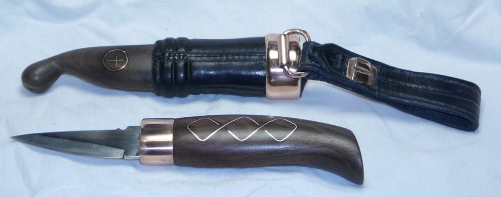
How I Made a Norwegian Style Knife

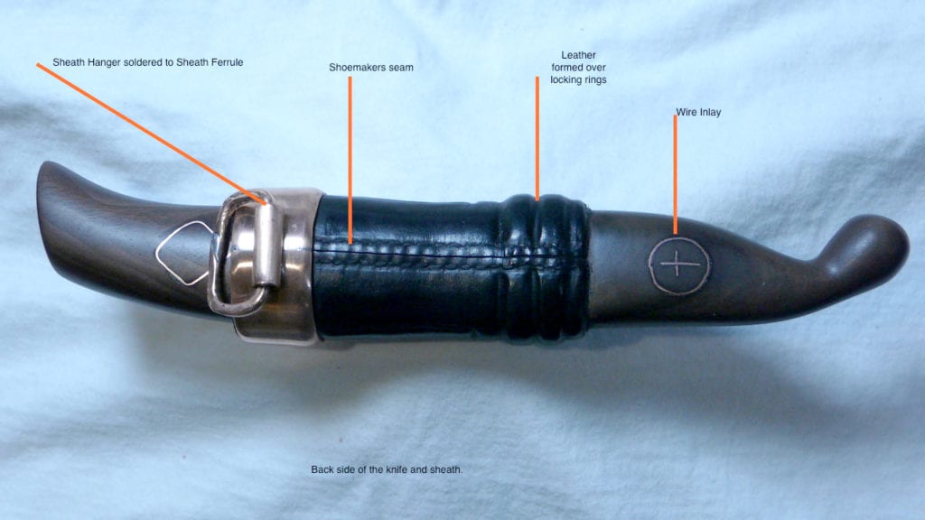
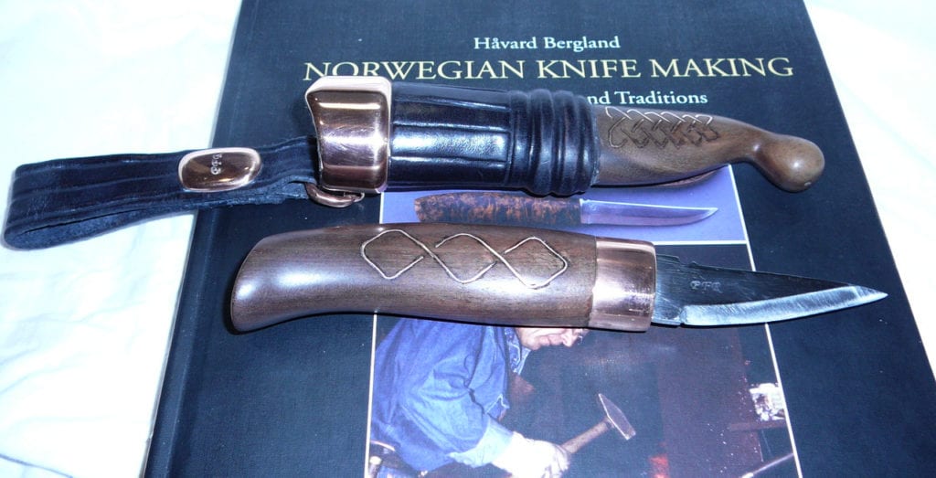
I highly suggest that handcraft makers perform a self-critique of items they make. This is my self-critique of a Norwegian-style knife, and it includes a discussion of my learning curve and problems and corrective actions for a test knife and sheath. For instruction, I used the book Norwegian Knife Making, Ancient Techniques and Traditions by Håvard Bergland and highly recommend this resource. It’s available at Vesterheim Museum Store. Taking a class is also a great option for support. I made every part of this knife.

knife and sheath made by Paul Rochrbarcer

Blade with Touch Mark

This blade was forged from 1018/1084/1018 steel in my coal fired side blast forge. After forging and heat treating, the soft steel sides were draw-filled to remove all hammer marks and pits from forging. The cheeks were ground down to the edge. A weld line appeared on one side of the blade, indicating a poor weld. This blade was forge-welded twice, once per side. My next blade will be welded twice per side for a total of four welding heats.                                                  

I kept grinding until the line was gone, which resulted in a rather pointed blade. The blade was sharpened at a 20-degree angle per side, which makes the edge strong at the expense of sharpness. Honing with a Hard Arkansas stone solved the sharpness question. The blade will shave hair and slice paper with great ease. Knife blades edges are usually ground for an included angle of 30-40 degrees. 

After the blade was mounted in the handle, it was used to carve the wood bottom of the sheath. The blade’s sharp point worked well to carve curved and flat surfaces. The edge stayed sharp!

Handle

Walnut was my choice of wood. Walnut carves, sands, and takes a Watco Oil Finish nicely. From Håvard’s book, I selected this handle design that fits my hand perfectly. 

The handle was rough-shaped, and the tang slot made. Then, the recess for the ferrule was carved in. Fitting the ferrule to the existing recess cut in the handle was difficult. For my next knife, the ferrule will be made first and then the oversized wood handle cut down to fit the ferrule.

The ferrule’s dimensions were made by carefully measuring the carved recess in the handle.  The annealed copper water pipe was cut to a rough shape using tin snips and then filed to dimension. The measured length had an extra 1/16” added to make a scarf for silver brazing.

The scarfs were filed at a 45-degree angle for an overlap to give more material to be wet with the braze than if the ends were squared off and butted. The joint was fluxed, a piece of silver braze inserted in the joint and the joint was heated to about 1100 degrees, a dull red color to melt the silver braze. 

The top cap of the ferrule was made from a flattened piece of annealed copper. The slot for the Ricasso was drilled/sawed/filed to an exact fit. The blade was inserted into the handle, the copper side ring part of the ferrule was pressed on the handle and the top cap slid on the blade. I had a fat place in the tang, which prevented the top cap from being slid over the tang. This problem of an extra fat place in the tang will be eliminated in the next knife.

A scribe was used to mark the circumference of the ferrule on the top cap’s bottom. How to solder the top cap on without melting the ring’s brazed joint was the next problem. The silver braze melted at about 1100 degrees. With the copper being thin, reaching 1100 degrees was quick, so the question was—What was the best solder to use? Choice: plumber’s solder, 95% tin/5% silver melts at 400 F, or electrical solder SN63, 63% tin and 37% lead, melts at 360 F. The SN63 was selected as it wets the surface much better than the plumber’s solder. The top cap was aligned, clamped together, fluxed, and soldered. The joint was perfect! The blade fit was perfect! 

Finished Ferrule with Top Cap

The completed ferrule was filed, sanded, polished, and then fit to the handle. The blade and ferrule epoxied into the handle. This step should have been delayed until the wire inlay step was completed.

Wire Inlay in the Handle and Sheath Wood Bottom

I chose wire inlay to make the knife different. I had some experience with wire inlay in steel and including it in wood is a similar process. Cut a groove, insert the flattened wire, and wet the wood, which swells and locks the inlay in place.  

It turns out wire inlay isn’t that easy! First, I flattened the 20-gauge copper wire with a hammer to be about 0.015” thick. Then the wire was work-hardened, which required the ribbon to be annealed after problems surfaced.

The simple Celtic design was penciled on both sides of the handle and the wood sheath bottom. I used x-acto blades and re-ground pieces of hacksaw blades to punch the groove into the handle. My first attempt was tried with the copper ribbon still work-hardened. As the handle is a curved surface, the stiffness of the ribbon was enough to pop the ribbon out of the groove as the ribbon was being inserted further along the groove. I finally used the annealed ribbon for the inlay. The initially inserted wire, however, had damaged the width of the groove, causing several gaps between the wire ribbon and wood.

The handle was sanded to 600 grit, then soaked in Watco Oil for overnight, and finally buffed.

sheath made by Paul Rochrbarcer with labels
sheath made by Paul Rochrbarcer

Wood Bottom of Sheath

The sheath’s wood bottom is made from a piece of walnut sawed, 1/3 rd. for the top and 2/3 rds. for the bottom thickness. The blade was inlet per Håvard’s instructions. From past experience, the wood bottom never solidly locked into the leather. Knifemaker KJ Groven sent pictures of his knife work that showed two wood rings at the top of the wood sheath bottom. When the leather dried and was worked into the rings, the wood was solidly locked to the dried leather. 

I made my wood rings just a little too large. The next sheath will have the rings less than 1/16” high and 1/8” wide with a 1/8” spacing between rings.

The wood bottom was also chosen for Celtic pattern Wire Inlay using 20-gauge copper wire flattened ribbon. Two problems surfaced. The ribbon once inserted, had to be held down on one end while being pounded in at the other end to keep the ribbon formed in the groove. During cutting the groove, one square piece chipped out and had to be glued back in. 

Leather Upper Section of Sheath

I used half-tanned leather from Thompsons for the upper section of the sheath. The center of the leather is rawhide. Håvard’s book described how to cut a groove in the flesh side of the leather, then mold recesses of the design in the exterior. This process worked well—when the leather was drying the design grooves and the leather around the two rings were pressed in place. 

Vertical grooves were formed by cutting grooves in the flesh side of the leather.

Shrinking Process of Wet Leather 

The handle was wrapped with a layer of plastic electrical tape and the blade was well greased. The electrical tape is slick plus it adds to the circumference of the handle. Once the leather is dry, the tape is removed, and the handle can be easily removed or inserted into the sheath with a click.

The seam came out almost perfect! The shoemaker’s stitch was eight stitches per inch with the awl punch through holes at the top of the rawhide. The seam is straight, tight, and flat. 

Shoemakers Seam

The sheath ferrule was a challenge! To determine the ferrule’s circumference, the handle was reinserted into the leather. Layers of electrical tape were added so the handle actually pressed out on the leather. This added circumference is necessary so the handle can pass through the ferrule’s constriction area.

The outer circumference of the leather was measured using three turns of masking tape plus 1/16” for the chamfer overlay. The annealed copper sheet was pressed around the sheath with the handle inserted. 

With the ends chamfered 45 degrees for an overlap, the ferrule’s joint was silver brazed. Now the ferrule wouldn’t pass over the leather! It was too small plus the top of the sheath was a little larger than the ferrule’s bottom. The solution was to tap lightly all around the copper ferrule on the anvil horn, until it fit over the leather. The bottom of the ring was now too large so it had to be reduced in circumference. How? I made a rounded top stake for my anvil. The ferrule’s bottom edge was placed about 3/32” above the top of the stake. Using a hammer, the edge was hammered over, which caused folds between the initial hammering locations. Now, all that was required was to hammer the folds flat. Once the bottom edge was rounded, the top edge was also rounded using the same process. The ferrule was finished by filing, sanding, and buffing.

Belt Loop

A 7/8”-wide section of the annealed copper was rolled onto a tube over the edge of the anvil. Then the bottom junction of the copper tube was filed to fit the contour of the ferrule. The tube was soldered on, using SN63 solder.  

The Copper Tube Soldered to the Ferrule

A copper wire loop was bent to fit the tube and the ends met, well centered. The ends were chamfered at a 45-degree angle and soldered using SN63 solder. 

The vegetable-tanned leather belt loop strap was made with edge leather tooling. Initially, a paper pattern was made to determine the dimensions of the strap. 

medallion on sheath made by Paul Rochrbarcer

Medallion

The belt loop is held together with a medallion with a PFR touch mark riveted through the strap. The domed medallion was made by cold forging an oval-cut piece of flat annealed copper over the top of the anvil stake. The process was simple—pound the copper down, then pound the folds down and finish by tapping all around to make the rollover even. My touch mark was stamped into the medallion. Filing, sanding, and buffing finished the top of the medallion.

The medallion is held on with a flat split rivet. The rivet is soldered to the back of the medallion using SN63 solder. A backing plate was made so the ends of the flat rivet can pass through and then be forged over.

Conclusions

Self critiquing is a valuable tool to improve your work skills. Make a written record for future reference. Since you made it, you know where to find the good, bad, and ugly. Think each step through. If the process doesn’t work as expected, think out the solution, ask an expert in that area of skill, read about how to do it, and view DVDs and Youtube videos of how others did it.

The goal is simple: “Make each item better than the one before it”

Paul Rohrbacher, an avid metalworker from Monticello, Iowa, has taken a number of forging and knifemaking classes at Vesterheim Folk Art School.